
-
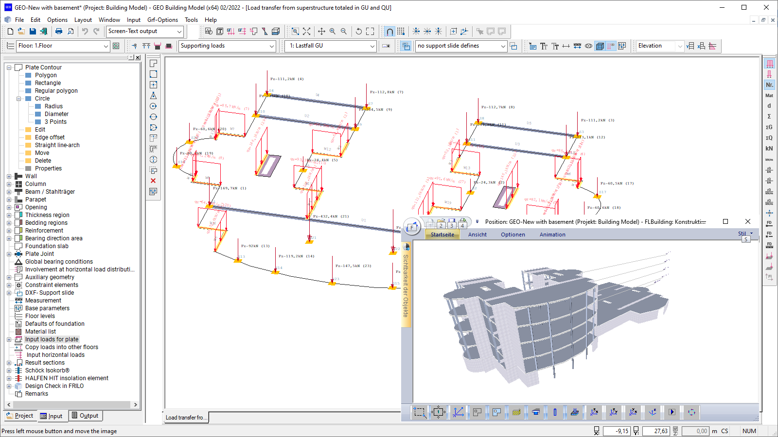 Representation of transferred superstructure loads
 -
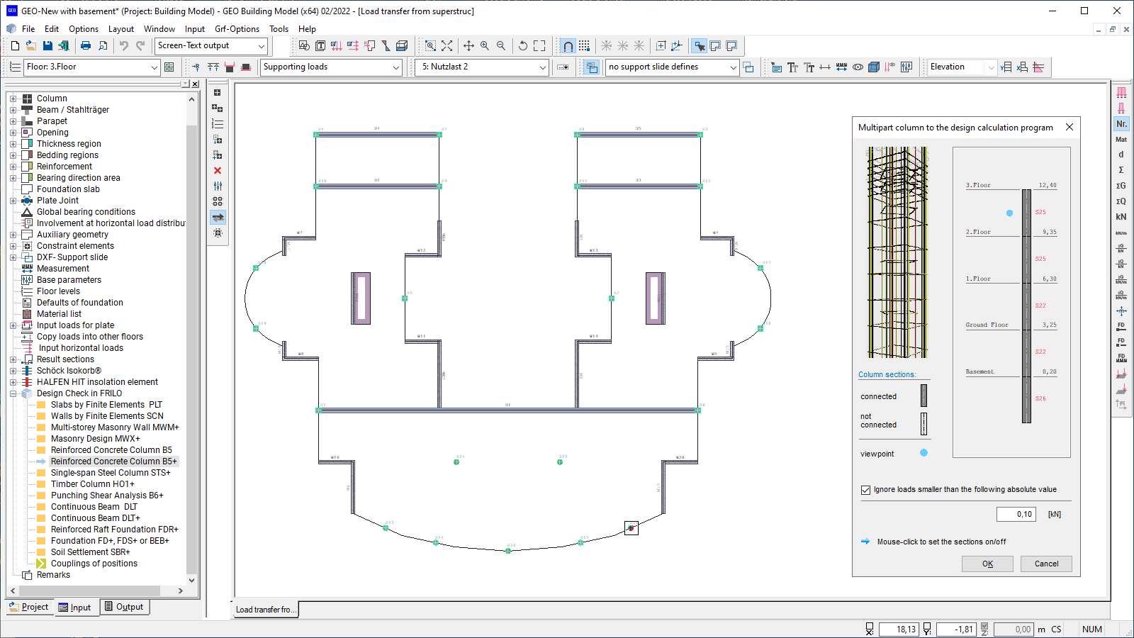 Load transfer to design programs (B5+ in the example)
 -
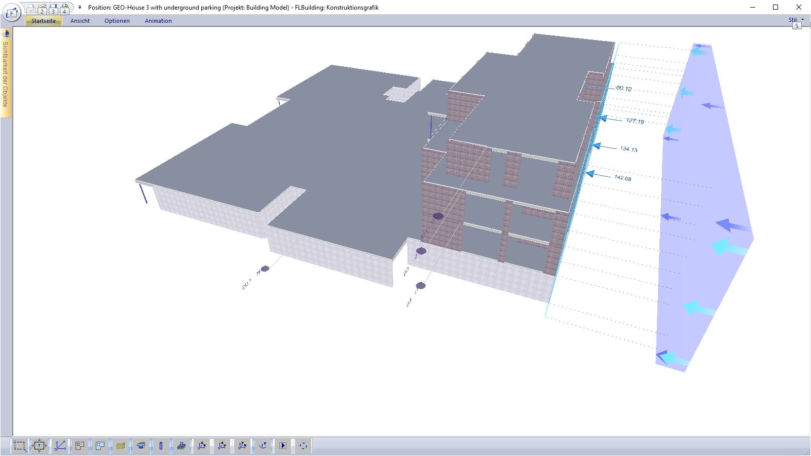 3-d representation (wind loads in the example)
 -
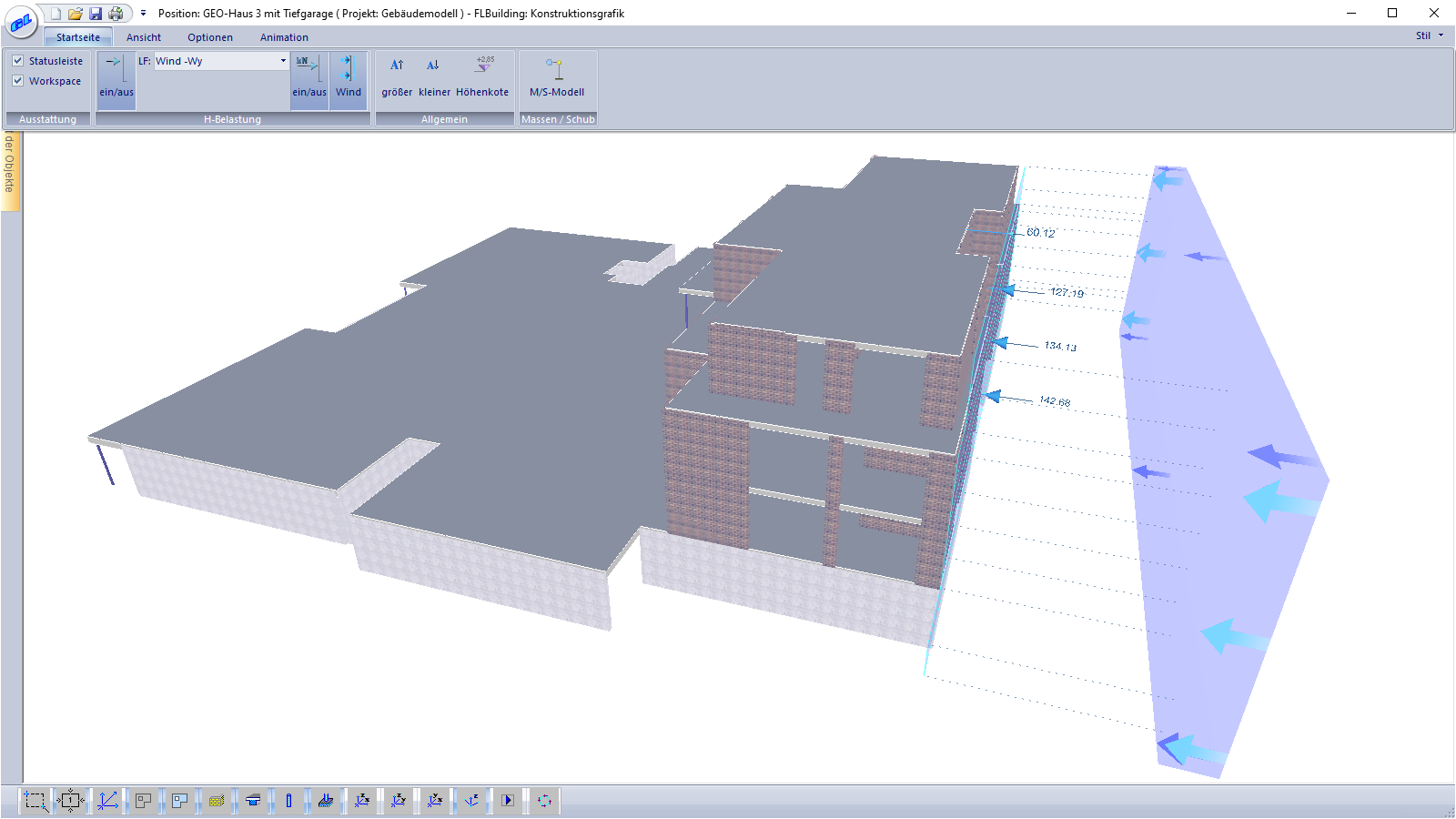 3D-Darstellung (hier mit Darstellung der Windlasten)
Building Model
GEO
Structures typical in massive building construction are mapped as global load-bearing structures with all structurally relevant components and loads. The building is modelled storey by storey. During this process, mapped storeys can be copied and further edited. Automated processes such as the determination of the horizontal loads and of the self-weight from the material data provided ensure a quick determination of the loads for the intended foundation. A floor slab, foundations, or a mixture of both can be defined for this purpose. Different foundation levels can also be implemented without any problems. A 3-d visualisation supports the control of the geometry and the loading. The scope of performance depends on the purchased add-ons.
Discover more products from the FRILO portfolio now!
SHOW MOREInput
Most data are entered interactively in the graphical user interface. To support this, DXF slides can be read in and self-defined auxiliary structures or auxiliary grids can be used. Thanks to a locally definable coordinate system and direction-oriented data entry, points/components can be defined easily and accurately via the graphical user interface or by entering numerical coordinates.
The Undo/Redo functionality allows work steps to be undone/restored, which supports a safe and effective workflow. Various import options, for example via the FRILO BIM-Connector®, top off the data entry.
Special features of the program
Coupling:
If a component is transferred from GEO to another FRILO program for the design, the user can register this item in the building model as a coupled (linked) item. If the corresponding component is accessed subsequently, this item is proposed before the transfer. In most design programs, a coupled item can be used as a template to specifically adopt or adjust properties and loads.
Instability examination:
In order to assess the rotational and lateral stiffness of the building, instability factors are determined. If these are complied with, a more accurate verification in a second-order analysis can be dispensed with.
Bemessung
General
An extensive graphical and tabular output for the creation of structural analysis documents in A4 format is provided. Moreover, all graphics can be put out in the so-called drawing format. Various user-definable title blocks can be used.
Output
The output profile offers a variety of setting options to create an individual structural analysis document. The scale is freely selectable.
Übergabemöglichkeiten
Automatic transfer of the components to the design programs inclusive all loads and action groups:
- Slabs by Finite Elements (transfer of floor slab & all relevant components)
- Walls by Finite Elements SCN (transfer of reinforced concrete walls)
- Multi-storey Masonry Wall MWM+ (transfer of walls from masonry)
- Masonry Design MWX+ (transfer of walls from masonry)
- Reinforced Concrete Column B5+
- Single-span Steel Column STS+ (transfer of cross sections & loads)
- Timber Column HO1+ (transfer of cross sections & loads)
- Punching Shear Analysis B6+
- Continuous Beam DLT+ (transfer of nodal loads from FE calculation)
- Reinforced Raft Foundation FDR+ (transfer of loads at the base of the walls)
- Isolated Foundation FD+
- Strip Foundation FDS+
- Beam on Elastic Foundation BEB+
- Soil Settlement SBR+
For most interfaces, the vertical support reactions can be added in two so-called superstructure load cases (GU for permanent loads and QU for live loads) or transferred as load case-specific loads in individual load cases. The action groups and alternative groups required for the superposition are also exported.
Import options
- The basic geometric data of an entire model can be imported directly via the FRILO BIM Connector®
- Slabs defined in the Finite Elements program PLT can be imported with all loads and geometric data
- Moreover, entire building systems can be transferred via the Wind Loads program WL
- Via a direct interface, CAD data can be imported from GLASER -isb cad- and further processed on this basis
- Also from Allplan, data of the PLT program (Slabs by Finite Elements) can be imported into the building model, if the structural components have been processed appropriately in Allplan.
- Moreover, geometry data in the form of auxiliary constructions can be imported via a DXF interface from all common CAD programs. These data can be used in the program via a snap function supporting the easy entry of the geometry.
Export options
- Graphical results can be exported to a DXF file
- The user can create SAF files to transfer data to SCIA, for instance.
- Load calculations, section and stress compilations as well as the quantity survey can be exported to an Excel or a CSV file
- Stored GEO items can be read into the Wind Loads program WL
Reinforced concrete
- DIN EN 1992, DIN 1045 / DIN 1045-1
- ÖNORM EN 1992, ÖNORM B 4700
- UNI EN / NTC 1992
- BS EN 1992
- PN EN 1992
Masonry
- DIN EN 1996, DIN 1053-1/-100
- ÖNORM EN 1996
- BS EN 1996
Wind loads
- DIN 1055-4, EN 1991-1-4 (DIN, ÖNORM, BS)
Sway imperfection
- EN 1992 (DIN, ÖNORM, BS)
- NTC EN 1992
- PN EN 1992
- EN 1992
- DIN 1045 / DIN 1045-1
- ÖNORM B 4700
Earthquake
- DIN 4149-2015, EN 1998-1
- DIN EN 1998-1
- ÖNORM EN 1998-1
Materials for steel columns as per
- DIN EN 1993, DIN 18800
- ÖNORM EN 1993
- BS EN 1993
Additional options
Horizontal Load Transfer GEO-HL
With the optional add-on module GEO-HL, horizontal loads generated by wind, inclination and earthquakes can be determined. The wind loads can be calculated depending on the building geometry and the specified wind parameters. Sway imperfections are automatically generated from the calculated vertical loads. The horizontal loads are distributed over the bracing components proportionally to the bending stiffnesses. A contribution to the horizontal load transfer can be defined for groups (e.g. only for reinforced concrete walls) or for individual components.
Earthquake GEO-EB
With the optional add-on module GEO-EB, seismic loads can be calculated in accordance with DIN EN 1998-1 and DIN 4149, 6.2.2 for Germany or in accordance with ÖNORM B 1998-1:2006/2011, 4.3.3.2 for Austria. The seismic loads are determined using the simplified response spectrum method.
The user can either freely define the basic values for the determination of the soil acceleration response spectrum or set them automatically via the selection of a municipality. The contributing vertical loads can be taken into account from a specific selectable floor level on. Various approaches are available to determine the basic vibration duration. After the calculation, the stress behaviour and the determined seismic shares can be displayed graphically for each individual component.
Quantity Survey GEO-ME
The optional add-on module for the determination of the quantities is controlled via the output profile. The user can define the tabular output individually for the different materials and components as well as for individual storeys or even across storeys. The program does not determine the reinforcing steel quantities.
The results can optionally be exported to an Excel folder or a CSV file.
Load transfer
Vertical load transfer:
The load calculation is carried out storey by storey from top to bottom, whereby the loads of the upper storey are passed on to the storey underneath.
Load types:
The available loads are point, line and area loads. For line and area loads, a distinction can be made between constant and non-constant loading.
Moreover, temperature loads can be considered. All loads are entered in load cases. These load cases are assigned to action groups already in the building model.
Specialities:
The user can subsequently copy load cases from one storey to another. In addition, an automatic transfer of loads from a stored calculated GEO item is available. In the transfer process, the support reactions acting at the base of an existing item are transferred to a selected storey. The user can choose whether the vertical support reactions are added up in two so-called superstructure load cases, each with a constant progression, or whether they are transferred as load-case specific loads in individual load cases.
In the building model, the self-weight of all load-bearing components is automatically considered.
Horizontal load transfer:
See tab “Additional options”.
Components & material
Slab:
All floor slabs can be defined as reinforced concrete slabs. Different thicknesses, different concrete qualities, and different load-bearing directions (uniaxial and biaxial) as well as torsionally resilient and torsionally stiff elements can be defined. The slab is supported by walls and columns or, in the case of base slabs, rests on elastic springs. By defining slab joints, bearing direction areas, reinforcement areas and subgrade areas, the user specifies additional properties that are included in a later design with the Slabs program PLT.
Walls:
Walls are used as linear supports for the slab and can be included as rigid or elastic supports. The user can freely define the elastic support or have it automatically determined from the geometry and the material properties. Masonry and concrete are available as materials. Walls can optionally be defined individually or as a connected so-called “wall pillar”.
Columns:
Columns are used as point-type supports for the slab and can be included like the walls as rigid or elastic supports. The user can freely define the elastic supports or have them automatically determined from the geometry and the material properties. Masonry, concrete, steel, and timber are available as materials.
Beams:
Beams are used as linear stiffeners for the slab. Suspender and downstand beams can be defined. The user can select a concrete quality that differs from the slab concrete quality. In addition to suspender/downstand beams of reinforced concrete, also steel beams can be defined as suspender/downstand beams. All common steel shapes are available for selection.
Parapets:
In contrast to suspender/downstand beams, parapets are just used to supplement the self-weight. Masonry and concrete are available as materials. Concrete parapets can also be defined as load-bearing structures. Internally, they are treated like downstand beams in this case.
Support resources
Warning: Undefined array key "Video "Schnittstellen"" in /var/www/staging.frilo.eu/user/htdocs/wp-content/themes/blank/single-produkte.php on line 607
News

“With the FRILO Suite, we benefit from the use of all programs”
With the switch to the FRILO Suite, the engineering office concon has decided to rely on the FRILO subscription model. The reasons of the long-standing customer are manifold.
FRILO & CARBOrefit® | The calculation with carbon concrete pays off
With CARBOrefit® an process that enables renovation and reinforcement with carbon concrete has been integrated into the FRILO Software.