Continuous Beam
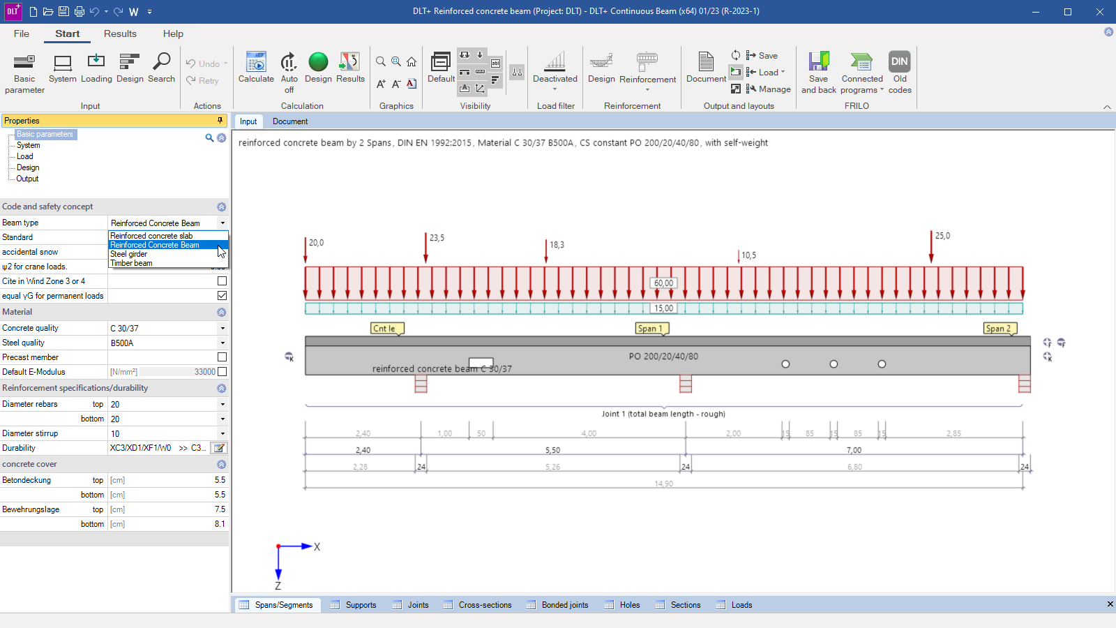
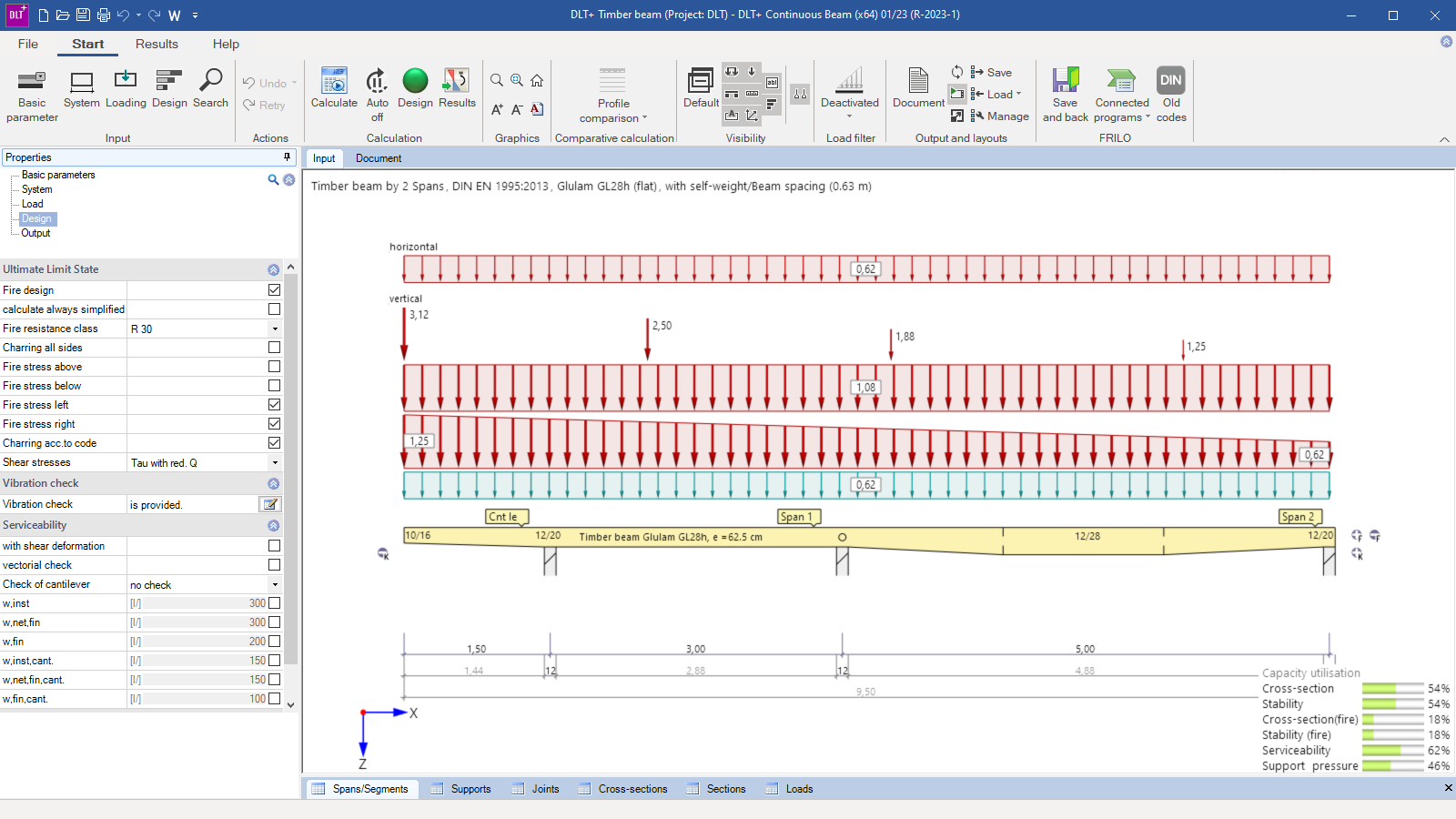
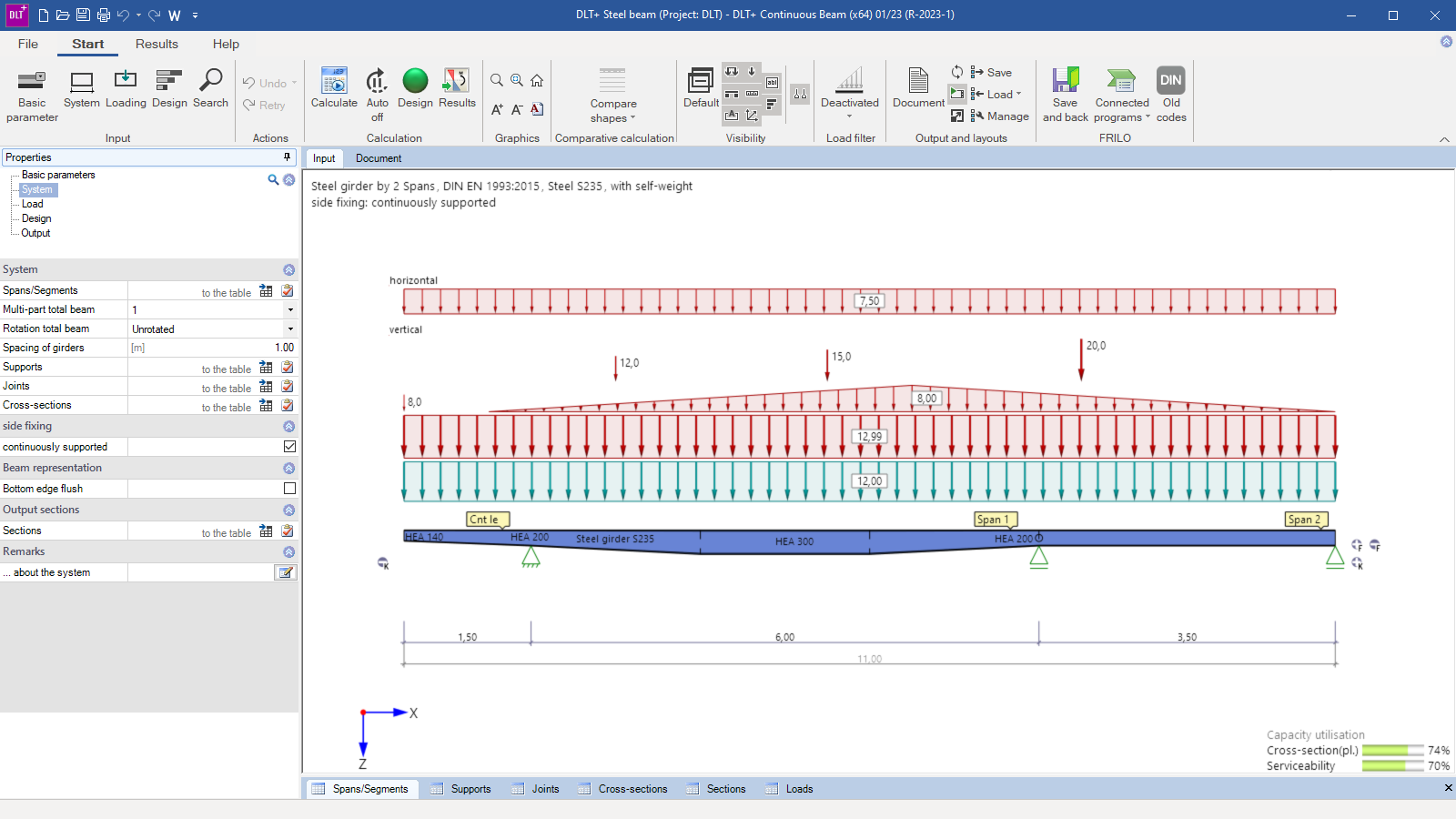
DLT+ can be used to calculate single-span and continuous beams for reinforced concrete, steel and timber with an unlimited number of spans, with or without cantilevers. Cross-sections can be constant or variable. Joints are also possible. In addition to the optically adapted interface, easier operation, a clear and detailed customizable output, the program offers a completely revised interactive reinforcement guide.
Discover more products from the FRILO portfolio now!
SHOW MOREMaterial
- Reinforced Concrete
- Steel
- Timber
Beam types
- Reinforced concrete slab (with reinforcement layout as additional option BTM-BEW)
- Reinforced concrete beam (also biaxial as additional option BTM-2 and with reinforcement layout as additional option BTM-BEW)
- Steel beam (also biaxial as additional option STM-2)
- Timber beams (also biaxial as additional option HTM-2)
Depending on the selected material, the cross-section definition is adjusted. Depending on the material, haunches and cross-section discontinuities, block-outs or multi-part/rotated/reinforced cross-sections can be defined, for example. The selection from the FRILO steel database is also available for steel cross-sections.
Loads
Standard loading and multi-span loading can be defined as uniformly distributed load, concentrated load, concentrated moment, trapezoidal load and triangular load.
Detailed information
DLT+ combines all beam types/materials of the individual programs BTM+, HTM+ and STM+ in one program.
Therefore, you will find detailed information under
Continuous Beam Concrete BTM+
Continuous Beam Timber HTM+
Continuous Beam Steel STM+
General
For concrete, steel and timber, the program carries out the design or the stress analysis for the preselected cross-section dimensions.
Reinforced Concrete
- Automatic calculation of the effective slab width
- Calculation of the deformations in state II for reinforced concrete cross-sections with standards based on the partial safety concept
- Crack width verification (limit diameter) and stress analysis
- Consideration of the durability requirements
- Calculation and consideration of the creep coefficient and the shrinkage strain in the serviceability analyses
- Verification of the shear joint for slabs and T-beams
- You can perform an analysis of the connection of the compression flange (shear joint analysis) for T-beams
Timber
- Optionally, shear deformations can be considered with timber beams
- Vibration analysis
- Hot design
- Stability analysis
Steel and timber
- Optimization of the dimensioning and design with steel and timber beams
- Stability analysis for steel girders
Add-on modules
- BTM-BEW: Reinforcement layout for reinforced concrete beams an slabs
- BTM-2: Biaxial effect of actions on reinforced concrete beams
- HTM-2: Biaxial effect of actions on wooden beams
- STM-2: Biaxial effect of actions on steel beams
Document file formats
- Word
- Printer
Output
- Brief
- Minimum
- User-defined
Load transfer
- Reinforced Concrete Column B5+
- Timber Column HO1+
- Single-span Steel Column STS+
- Reinforced Concrete Corbel B9+
- Reinforced Concrete Half Joint B10+
- Framework RSX
- Continuous Beam Concrete BTM+
- Continuous Beam Steel STM+
- Continuous Beam Timber HTM+
- Timber Compression TB-HHS
- Lateral Torsional Buckling Analysis BTII+
Data transfer
The analysis of steel beams for lateral torsional buckling and elastic-plastic analyses can be performed per data transfer to the program Lateral Torsional Buckling Analysis BTII+.
Reinforced concrete
- EN 1992 (NA-D/A/GB/IT/PN)
Steel
- EN 1993 (NA-D/A/GB/PN)
Timber
- EN 1995 (NA-D/A/GB/IT/PN)
Support resources
News
Material-independent calculation of continuous beams
The FRILO program Continuous Beam can be used to calculate single-span beams and continuous beams of concrete, steel and timber with any number of spans and with or without cantilevers.
FRILO 2023-1: The latest version saves time and contributes to climate efficiency
FRILO Software GmbH has successfully delivered the software version 2023-1. With the update, the vendor of innovative solutions for structural analysis and design launches four new PLUS programs – including DLT Continuous Beam.

